Introduction and Industry Overview
The market for motorized children's ride-on vehicles has expanded dramatically over the past decade, driven by advances in battery technology, safety engineering, and consumer demand for realistic driving experiences. Among the various control interfaces found on modern electric cars, the foot pedal accelerator remains the quintessential feature that bridges the gap between toy simulation and authentic driving simulation. For wholesale distributors, retail buyers, and commercial operators, understanding the internal mechanics and electrical architecture of the foot pedal accelerator is crucial for product evaluation, quality assurance, and customer support.
When a young driver presses down on the foot pedal of a ride-on vehicle, a sophisticated yet accessible sequence of electromechanical events takes place. Unlike full-sized automotive systems that utilize complex throttle bodies, fuel injectors, or sophisticated engine control units (ECUs), ride-on cars operate on direct current (DC) electrical circuits designed for simplicity, durability, and safety. However, engineering a reliable foot pedal mechanism requires careful consideration of mechanical resilience, electrical load management, tactile feedback, and fail-safe design. This comprehensive technical guide explores how foot pedal accelerators function, examining the underlying circuitry, mechanical switch mechanisms, voltage regulation, safety integrations, and maintenance considerations for B2B procurement professionals and industry stakeholders.
The Evolution of Control Systems in Ride-On Vehicles
Early generations of motorized ride-on toys relied on rudimentary on-off switches mounted on the steering wheel or dashboard. These early designs provided binary operation: pressing the button delivered full battery voltage immediately to the electric drive motor, resulting in sudden, jerky acceleration that could startle young children and place excessive mechanical stress on the gearbox and wiring harnesses.
As consumer expectations evolved and safety standards matured, manufacturers transitioned toward foot-operated pedal mechanisms. The foot pedal introduced ergonomic naturalism, allowing children to operate the vehicle using the same foot-eye coordination required for real automobiles. Furthermore, the integration of foot pedals paved the way for advanced electronic innovations such as proportional speed control, soft-start circuitry, and integrated braking systems. Today, evaluating a ride-on vehicle's acceleration system involves analyzing not only the physical pedal structure but also the underlying electronic control unit (ECU) or relay switch box that governs power transmission.
Core Mechanical and Electrical Components of the Foot Pedal
To understand how acceleration is achieved, one must examine the primary components housed within or connected to the foot pedal assembly. While specific designs vary across manufacturers, production standards, and vehicle categories (such as sports cars, SUVs, and utility tractors), most systems incorporate a standardized set of electromechanical elements.
1. The Mechanical Pedal Housing and Return Spring
The physical pedal interface consists of a molded plastic lever hinged to the vehicle floorboard or footwell. Beneath the pedal cap lies a heavy-duty return spring. This spring ensures that the pedal immediately returns to its resting, unpressed position the moment the driver lifts their foot. This mechanical restitution is a vital safety feature, instantly cutting off power to the drive motors and initiating deceleration or braking depending on the circuit configuration.
2. The Microswitch or Potentiometer
At the heart of the electrical activation is either a spring-loaded microswitch or, in more advanced models, a rotational potentiometer (or Hall-effect sensor).
* Microswitch Systems: Most standard 6V, 12V, and many 24V ride-on cars utilize a heavy-duty microswitch. When the pedal is depressed, the internal plunger of the switch is compressed, closing the electrical circuit and permitting current to flow from the battery through the control board to the drive motors. When released, the circuit opens, breaking the electrical flow.
* Potentiometer and Hall-Effect Systems: High-end or variable-speed models may employ a potentiometer or magnetic Hall-effect sensor. As the pedal travels downward, variable resistance or magnetic field changes signal the control module to modulate the voltage delivered to the motor, enabling gradual acceleration rather than binary on-off operation.
3. Wiring Harnesses and Connectors
The pedal assembly is connected via robust wiring harnesses to the central control module, relay box, or battery terminals. These wires are insulated to withstand mechanical vibration, moisture, and foot traffic within the footwell. High-quality manufacturing standards ensure that wire gauges are appropriately rated for the maximum current draw of the vehicle's drive motors.
Circuitry and Power Transmission Pathways
The flow of electricity from the power source to the wheels depends entirely on the state of the foot pedal switch. To fully appreciate this mechanism, it is helpful to trace the electrical pathway from the energy storage unit to the final drive assembly.
When the vehicle's main power switch is turned on, the system is primed. However, until the foot pedal is depressed, the circuit remains open at the microswitch junction. Pressing the pedal bridges this gap, completing the circuit between the battery (or fuse-protected distribution block) and the drive motor controllers.
In standard dual-motor rear-wheel-drive configurations, the closed foot pedal circuit simultaneously energizes both drive motors, ensuring balanced traction. In vehicles equipped with electronic control modules (ECUs), closing the pedal switch triggers a programmed startup routine. For further technical specifications or bulk purchasing inquiries regarding vehicle circuitry, Request a wholesale quote.
Comparative Analysis of Ride-On Acceleration Interfaces
Different ride-on vehicle categories utilize distinct acceleration methodologies tailored to user age, vehicle weight, and powertrain specifications. The following table provides a comparative overview of common accelerator configurations evaluated by procurement professionals.
| Acceleration Type | Primary Operating Mechanism | Typical Voltage Class | Performance Characteristics & Best Applications | Safety & Maintenance Considerations |
|---|---|---|---|---|
| Standard Foot Microswitch | Mechanical plunger closes direct circuit on depression | 6V to 12V | Binary on-off power delivery; ideal for entry-level toddler sports cars and lightweight cruisers. | High mechanical durability; requires periodic check for stuck pedals or debris in footwell. |
| Variable Potentiometer | Resistance-based sliding contact varying voltage output | 12V to 24V | Smooth, progressive acceleration mimicking real vehicles; suited for premium licensed models. | Sensitive to moisture and dust ingress; requires sealed housing and quality wiper contacts. |
| Dual Pedal (Gas & Brake) | Separate pedals for power engagement and electronic braking | 12V to 24V | Traditional driving simulation; lifting foot pedal disengages power while brake pedal engages dynamic braking. | Clear instructions needed for young users; dual switch maintenance required. |
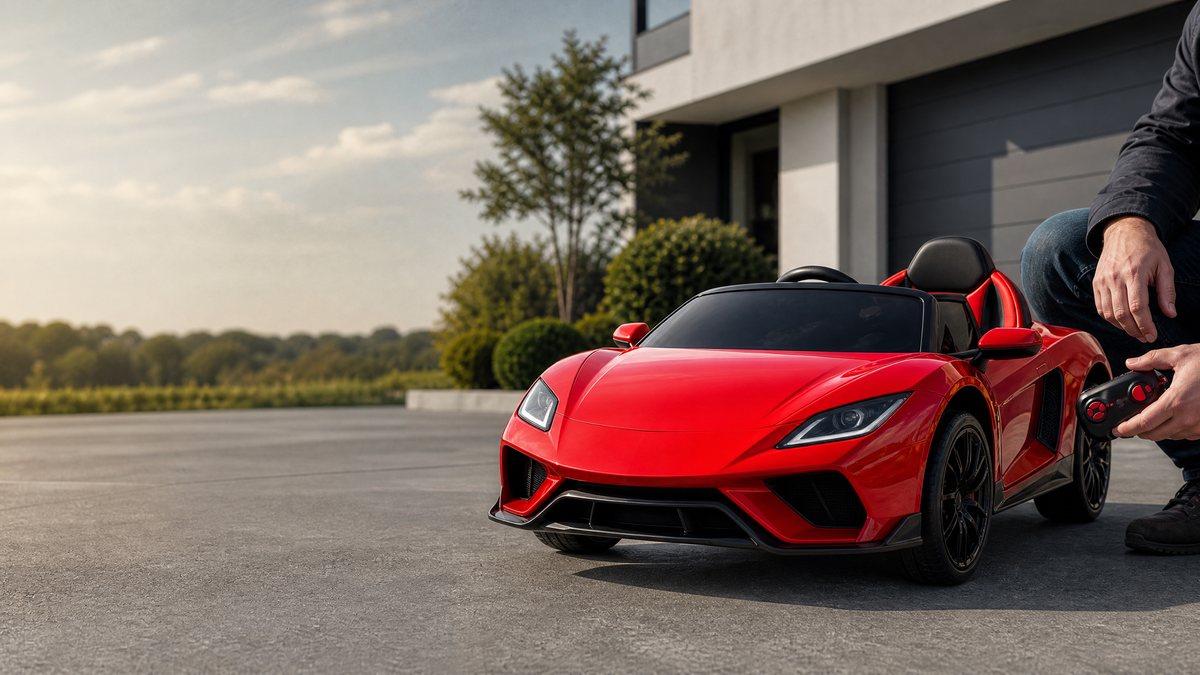
| Parental Priority Override | Remote transmitter signal overriding foot pedal input | 12V to 36V | Maximum safety control; remote transmitter commands take absolute precedence over manual foot pedal operation. | Requires verified pairing between transmitter and vehicle receiver; battery checks for remote unit. |
Safety Design Principles and Soft-Start Mechanisms
Safety engineering is paramount in the design of children's electric vehicles. Uncontrolled surges of electrical current can cause wheel spin, tire wear, gearbox stripping, and potential fright for young drivers. Modern ride-on car manufacturing incorporates several vital safety layers into the acceleration system.
Soft-Start Technology
Many contemporary vehicles feature a soft-start feature integrated into the control module. When the foot pedal is depressed, the control board intentionally ramps up voltage over a period of 1 to 3 seconds rather than delivering an instantaneous shock load to the motors. This protects internal nylon gears, extends battery lifespan, and provides a smooth, comfortable takeoff experience for the child.
Automatic Braking Upon Pedal Release
In most single-pedal configurations, lifting the foot off the accelerator automatically shifts the circuit into a regenerative or coasting stop state. By interrupting the forward circuit, the motor windings interact with the drivetrain to slow the vehicle safely to a halt, preventing coasting down inclines and ensuring intuitive vehicle control.
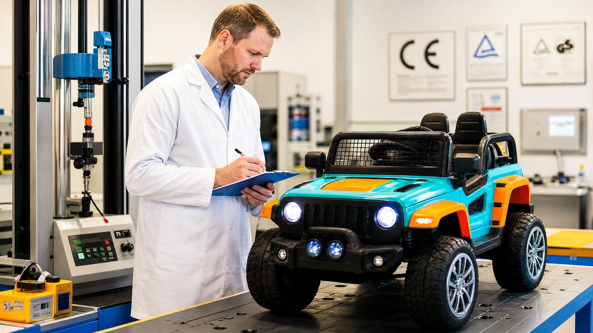
*Note on Safety Compliance:* All evaluations of electrical safety, mechanical shielding, and circuit protection must comply with applicable regional toy safety standards, such as ASTM F963 or EN 71, and should always be verified against the specific manufacturer's product manual and documentation.
Operational Scenarios and Environmental Factors
The performance and longevity of a foot pedal accelerator are heavily influenced by environmental operating conditions and usage scenarios. Wholesale buyers and commercial fleet operators must consider these factors when deploying ride-on cars in diverse environments.
Indoor vs. Outdoor Operation
Indoor environments (such as showrooms, nurseries, or home living rooms) provide controlled, clean surfaces that minimize dust and moisture ingress into the foot pedal microswitch housing. Conversely, outdoor environments (concrete pathways, park lawns, and asphalt driveways) expose the vehicle to particulate debris, grass clippings, and moisture. If dust or debris lodges within the pedal hinge or switch contacts, it can cause intermittent contact failure or a stuck pedal condition. Regular inspection of the footwell area is essential for maintaining optimal functionality.
Weather and Moisture Precautions
Electric ride-on cars are generally not waterproof. Operating vehicles in heavy rain, standing puddles, or damp grass risks water infiltration into the foot pedal microswitch and wiring connections, which can lead to electrical short circuits or switch corrosion. If moisture exposure occurs, adult supervisors must immediately turn off the vehicle, disconnect the battery source according to the manufacturer manual, and allow the components to dry completely in a well-ventilated area before further operation.
Troubleshooting Common Foot Pedal Acceleration Issues
When servicing or maintaining electric ride-on fleets, technicians and retailers frequently encounter minor acceleration faults. Understanding systematic troubleshooting frameworks ensures efficient resolution without compromising electrical safety.
1. Vehicle Fails to Move When Pedal is Pressed
* Initial Checks: Verify that the main power switch is turned on and that the battery is charged. Check if the vehicle is in parental remote-control lockout mode (if applicable).
* Switch Inspection: Inspect the mechanical foot pedal for physical obstruction, jamming, or failure of the return spring.
* Electrical Verification: Consult the manufacturer's user manual for approved diagnostic steps. If internal wiring or switch replacement is required, ensure that work is performed by qualified maintenance personnel using OEM-specified replacement parts. Never attempt to bypass safety fuses or tamper with high-current battery terminals.
2. Intermittent Acceleration or Delayed Response
Intermittent power delivery often indicates worn microswitch contacts, loose wiring harness connectors, or debris accumulation within the pedal assembly. Cleaning the footwell and verifying secure terminal connections typically resolves these symptoms.
Frequently Asked Questions (FAQs)
Q1: Can the speed of the foot pedal accelerator be adjusted manually?
A: In standard models, the foot pedal operates at a fixed preset speed or utilizes a pre-programmed soft-start curve determined by the factory control board. Some advanced multi-speed models feature a dashboard high/low speed switch, but the foot pedal itself generally triggers the selected speed profile rather than acting as an infinite throttle. Refer to your specific vehicle's user manual for model-level capabilities.
Q2: What should I do if the foot pedal remains stuck in the down position?
A: If the foot pedal sticks, immediately turn off the main power switch and remove the child from the vehicle. Inspect the pedal hinge and return spring for physical obstructions, dirt accumulation, or mechanical damage. Do not force the mechanism or attempt unauthorized structural modifications. Contact the manufacturer or qualified service personnel for guidance.
Q3: Are foot pedal accelerators waterproof for outdoor use?
A: No. While foot pedal housings are generally designed to resist minor dust and accidental liquid splashes, they are not waterproof. Operating ride-on cars in heavy rain, wet grass, or deep puddles can cause moisture ingress into the electrical switch and wiring harness, leading to malfunctions. Always store and operate vehicles in dry conditions as specified in the owner's manual.
Q4: How do foot pedal accelerators interact with parental remote controls?
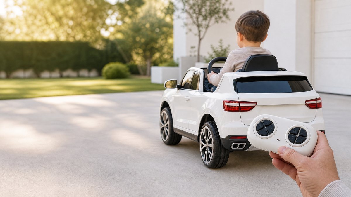
A: In most modern dual-mode ride-on cars, engaging the parental remote control overrides manual foot pedal input for safety reasons. When the remote control signal is active, pressing the foot pedal inside the vehicle is typically disabled until the remote override is released by the supervising adult. Check the specific pairing and operational instructions provided in the manufacturer's documentation.
Conclusion and Wholesale Procurement Guidance
The foot pedal accelerator is much more than a simple on-off switch; it is a critical electromechanical interface that dictates the safety, reliability, and enjoyment of an electric ride-on vehicle. For wholesale distributors and retail buyers, partnering with manufacturers who prioritize high-grade microswitches, robust wiring harnesses, reliable soft-start modules, and strict compliance with international toy safety standards ensures long-term customer satisfaction and minimal warranty claims.
To explore our complete catalog of certified electric ride-on cars, review technical specifications, or discuss volume pricing and container shipping options for your commercial enterprise, Request a wholesale quote.
Official References
1. U.S. Consumer Product Safety Commission (CPSC): Toy Safety Education and General Electrical Safety Guidelines for Motorized Children's Products. Available via official CPSC public safety portals.
2. ASTM International: Standard Consumer Safety Specification for Toy Safety (ASTM F963), covering electrical integrity, mechanical hazards, and switch mechanism durability.
3. European Committee for Standardization (CEN): Safety of Toys Standards (EN 71 series), detailing electrical property limits, maximum voltage specifications, and accessible component guidelines for electric ride-on toys.
*Disclaimer: All technical descriptions, operational guidelines, and safety protocols outlined in this article are provided for informational and educational purposes. Actual product features, electrical schematics, and operating parameters vary significantly by manufacturer, model, and production batch. Always consult the specific product rating plate, user manual, and authorized manufacturer documentation before operating, maintaining, or servicing any ride-on vehicle.*
Official references
Explore these external resources for current regulatory and trade guidance. Confirm requirements with the relevant authority before placing an order.
Ready to Start?
Factory-Direct · CE & ASTM Certified · MOQ from 50 Units
Our export team works with buyers in 60+ countries. Get a quote within 24 hours.
KR
Written by KidsRideCar
China's leading kids electric ride-on car manufacturer. 500,000+ units shipped annually to 60+ countries. CE, ASTM & EN71 certified.